


Last issue, we introduced the concept of Pulse Width Modulation (PWM), described how it works, and identified the main commercial systems available in North America. This issue will contain practical information on how PWM can be implemented on a sprayer on your farm.
What can PWM do?

Spray Quality:Since PWM systems can alter flow rate without affecting spray pressure, the user can select a spray pressure that meets their spray quality goals and expect this spray quality to remain constant throughout the field, regardless of travel speed.
Spray Drift Control: Although PWM does not by itself have any unique capabilities to reduce spray drift, it does make spray drift management easier. For example, the most accessible tool for reducing spray drift is to increase droplet size by reducing spray pressure. In a conventional system, the reduction of spray pressure can only be achieved with a reduction in travel speed because the lower spray pressure also reduces the overall flow rate. With PWM, the loss of flow with a reduction in spray pressure can be compensated by an increase in duty cycle (DC). As a result, lower pressures do not require a reduction in travel speed provided there is sufficient DC capacity in the system. Also, PWM systems use larger orifice nozzles, which naturally produce larger droplets.
Rate Control: A PWM system can be used for variable rate application. The spray volume, as determined by duty cycle, can vary as desired within its operational envelope without a change in travel speed.
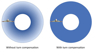
Turn Compensation: AIM Command Pro, Capstan Pinpoint, Raven Hawkeye, and John Deere ExactApply feature turn-compensation capabilities. During a turn, the outside boom moves faster than the inside boom, resulting in under- and over-application. A turn-compensated system can deliver additional flow to the outside, reducing the flow towards the boom end on the inside of the turn. In practice, there are limits to this feature. For example, the system’s average DC needs to be about 70 per cent to offer the maximum flexibility. Second, the diameter of the object being turned around must not exceed the width of the boom, or else the inside boom moves too slowly in relation to the outside boom. The system’s lag must also be minimal to avoid a counteracting effect during turn initiation and completion.
Sectional Control: In a PWM system, sectional configuration is determined by wiring and software, not plumbing. All section valves remain open during operation, and sectional shutoff is effected directly at the nozzle solenoid. Individual nozzle sectional control is offered by the AIM Command Pro and Capstan Pinpoint, as well as Hawkeye 2.0 HD and John Deere ExactApply. This feature may provide product savings when field margins are not straight, or fields feature obstacles resulting in significant overlaps.
Shutoff Response: The traditional nozzle check valve is designed to prevent nozzle dripping on boom shutoff. However, due to the presence of air pockets in most booms as well as the elastic nature of rubber hoses leading to the boom, the shutoff is delayed until the boom pressure reaches about 1 bar. This can take up to 10 seconds, resulting in unintended overspray and other safety concerns. In a PWM system, the solenoid shuts off the flow to the nozzle instantly, and conversely, turns it on instantly as well. The boom remains fully pressurized while the nozzles are shut off, allowing the spray patterns to be fully developed upon flow resumption.
Nozzle options
A pulsing solenoid creates short durations of low pressure inside the nozzle body, and this can result in poor performance of some air-induced tips. As a result, the PWM manufacturers have recommended that air-induced nozzles be avoided, and pre-orifice nozzles be used instead.
Nozzle selection process
The sizing of nozzles requires a small calculation from traditional spray calibration tables. Follow these steps:
1. Target a duty cycle of 70 per cent ± 10 per cent on average during operation. This permits the best travel speed flexibility. Say you want to apply 10 US gpa at 15 mph. In a conventional system, the 05 nozzle size could meet this flow at 40 psi. For PWM, the 06 size would operate at about 83 per cent duty cycle (0.5/0.6 = 0.83). Assuming a minimum DC of 20 per cent, a minimum travel speed of about 3.6 mph is possible. The 08 size would operate at 63 per cent DC (0.5/0.8=0.63), allowing a minimum speed at 20 per cent DC of 4.8 mph. Either option can work as long as the operator recognizes the travel speed limitations of both. Remember that the actual flow rate change is not directly related to duty cycle. Expect to see higher flows than calculated, especially for the smaller flow rate nozzles.
2. Calculate the travel speed range. The travel speed range of any nozzle selection and water volume can easily be calculated. The maximum travel speed is limited by the capacity of the selected nozzle and pressure at 100 per cent DC. The minimum travel speed can be assumed to be 20 per cent of that value, at which the system would be operating at 20 per cent DC. Assuming a user selected the 08 nozzle size at 40 psi in the above example, the maximum travel speed can be read from a traditional calibration chart, 24 mph. The minimum would be one fifth of that, 4.8 mph. Capstan has charts that show the theoretical travel speed range (assuming a direct relationship between DC and flow). For Raven and TeeJet, the charts were developed using actual flow measurements. These reveal that actual flows are slightly more than predicted, especially for smaller nozzles.
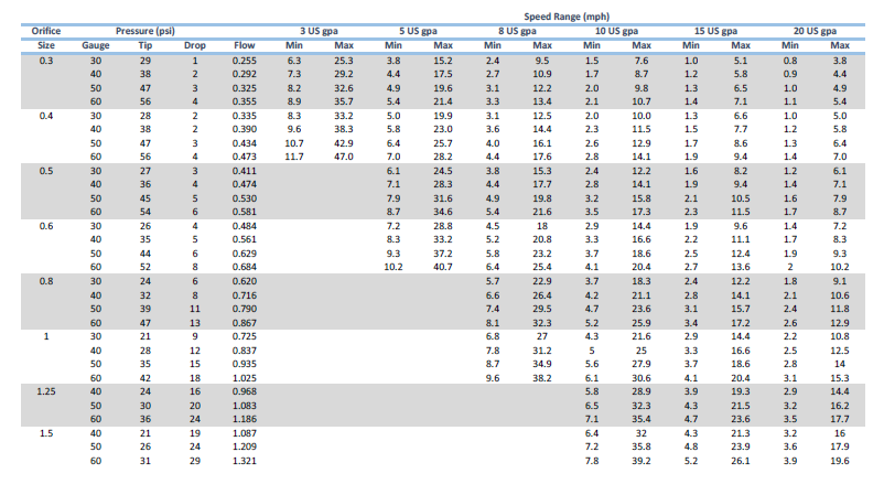
Theoretical travel speed ranges for various combinations of nozzle sizes and application volumes. Application rates have been lowered to account for pressure drop across the Capstan solenoid.
3. Consider the pressure drop across the solenoid. The pressure drop depends on the total flow through the solenoid, it varies from 3 to 5 psi for 04 flow rates to 5 to 13 psi for 08 flow rates for the Case, Capstan, and Raven products. If targeting 40 psi spray pressure, set the pressure to 40 psi plus these values. Traditional spray charts do not account for pressure drop across the PWM solenoids. When using a Capstan Ag system, always refer to the tip charts from Capstan Ag Systems, Inc. at capstanag.com, or www.sprayers101.com/capstan-calibration-chart-with-pressure-drop/ and when using a TeeJet system, refer to the charts at www.teejet.com. Both show the pressure drop at various flow rates.

Tom Wolf, Ph.D, P.Ag.
Tom Wolf grew up on a grain farm in southern Manitoba. He obtained his BSA and M.Sc. (Plant Science) at the University of Manitoba and his Ph.D. (Agronomy) at the Ohio State University. Tom was a research scientist with Agriculture & Agri-Food Canada for 17 years before forming AgriMetrix, an agricultural research company that he now operates in Saskatoon. He specializes in spray drift, pesticide efficacy, and sprayer tank cleanout, and conducts research and training on these topics throughout Canada. Tom sits on the Board of the Saskatchewan Soil Conservation Association, is an active member of the American Society of Agricultural and Biological Engineers and is a member and past president of the Canadian Weed Science Society. Twitter: @nozzle_guy


